Powered By Blogger

Jumat, 09 November 2012

lathe machine steps turning on

bramawan.blogspot.com

http://www.wikihow.com/Use-a-Wood-Lathe


How to Use a Wood Lathe


  1. The specification plate on the lathe in the illustrations.
    The specification plate on the lathe in the illustrations.
    Select a lathe suitable for your project. Bench top lathes can be ideal for turning small projects like ink pens and yo-yos, larger machines may be used for making spindles used in furniture and handrail styles. Here are some differences in wood lathe specifications:

    • Bed length is the distance between centers, or the maximum length of the stock that can be turned.
    • Swing is the term used to describe the largest diameter stock that can be turned.
    • Horsepower is the amount of torque the lathe motor develops, which in turn will determine how heavy an item can be turned without overloading this critical component.
    • RPMs are the revolutions per minute the stock can be turned. Here, note that most, if not all lathes have variable speed capabilities. A lathe with a very low speed range allows the user to start a piece of odd shaped, unbalanced stock without excessive vibration, and high speed machines can speed the work while making obtaining a fine, smooth finish easier to achieve.
    • Weight and composition. Heavier machines with cast iron beds and steel frames offer a good, solid work platform, but can be difficult to move if you are operating it in a crowded workshop where you will be storing it when it is not in use.
  2. 2
    Choose the lathe operation you are going to begin with. A simple task might be to turn a square or irregularly shaped piece of wood to a true cylindrical shape, often the first step to forming a spindle or other round item.
  3. 3
    Assortment of turning tools, including gouge, parting tool, larger gouge, and skew chisel, from left to right.
    Assortment of turning tools, including gouge, parting tool, larger gouge, and skew chisel, from left to right.
    Select the correct cutting tools for your objective. Lathe tools are called knives or chisels, sometimes interchangeably. They feature long, round, curved handles to afford a solid grip and sufficient leverage to enable the turner to control the cutting edge accurately with minimal fatigue. Common wood chisels simply are too short and are ill-designed for this purpose. Here are a few of the many types turning tools you may find:

    • A knurling gouge, used for cutting knurls or “vee” shapes into the work piece efficiently.
      A knurling gouge, used for cutting knurls or “vee” shapes into the work piece efficiently.
      Gouges. These usually have specially shaped cutting edges for performing particular cuts, such as bowl gouges, with concave, curved cutting edges to form the smooth, curved surface of a bowl, or vee, or knurling gouges for cutting grooves or knurls in wooden spindles.
    • Scrapers. These are often flat or slightly curved chisels for removing wood from flat or cylindrical shapes, or for roughing out a shape.
    • A parting tool, used to cut the work piece through, or part it.
      A parting tool, used to cut the work piece through, or part it.
      Parting tools. These are thin, vee tipped tools for cutting off work pieces.
    • Spoon cutters have a spoon shaped cutting edge and are also often used for shaping bowls.
    • Other tools you may encounter are skew chisels, fluted gouges, spindle gouges, and nose chisels.
  4. 4
    Learn the components of your lathe. A basic wood lathe consists of a bed, headstock, tailstock, and tool rest. Here are the functions of each of these parts.

    • This headstock has a number 2 Morse taper bore to hold the spur center.
      This headstock has a number 2 Morse taper bore to hold the spur center.
      The headstock consists of the drive train, including the motor, pulleys, belts, and spindle, and for a right handed turner, will be located on the left end of the lathe. Mounted on the end of the headstock facing the tailstock is the spindle and the spur center or for face turning such as bowls and plates, or other flat or face work, the face plate assembly.
    • This is the tailstock, the crank on the end forces the cup center into the end of the work piece.
      This is the tailstock, the crank on the end forces the cup center into the end of the work piece.
      The tail stock is the free spinning end of the lathe, and has the tailstock spindle and the cup center, as well as a hand-wheel or other feature for clamping or securing the work piece between the lathe centers.
    • This is a view of the tool rest.  It is a pretty massive steel assembly, to support the tool while cutting.
      This is a view of the tool rest. It is a pretty massive steel assembly, to support the tool while cutting.
      The tool rest is similar to a mechanical arm with a metal guide bar to support the chisel or knife used for turning the work piece. It usually can be adjusted by sliding the length of the bed at its base, with an intermediate arm that can swing from a parallel to a perpendicular position in relation to the lathe bed, and the upper arm, which holds the actual tool rest bar. This assembly has as many as three swivel joints, all of which tighten with a setscrew or clamp to keep it secure while turning is in progress.
  5. 5
    Read your owner's manual before proceeding with actual lathe work for specific instructions, features and detailed safety instructions. Keep your owner's manual handy for reference if you decide to purchase accessories for your particular lathe, for maintenance instructions, and for reference to capacities and specifications for your machine.
  6. 6
    Select a suitable piece of wood for your project. For a beginner, using a softwood like southern yellow pine, lodge-pole pine, or balsam fir may be a good idea. Look for a piece with fairly straight grain, and few, tight, knots. Never turn a split piece of stock, or one with loose knots, these may separate during turning, and become projectiles traveling at a significant speed.
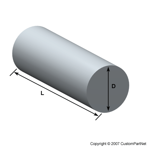
  7. 7
    Square the stock. For example, if you are going to begin with a piece of 2X4 lumber, rip it to a nominally square shape, such as 2X2. You can then chamfer, or bevel the square corners, effectively creating an octagonal piece, which will reduce the amount of wood that must be removed to reach your desired cylindrical shape.
  8. 8
    Cut the stock to the desired length. For a beginner, starting with a relatively short length, less than 2 foot long for an intermediate, or medium sized lathe, is a good choice. Longer work pieces are difficult to true, and maintaining a uniform diameter along the length of a longer piece can take a lot of work.
  9. 9
    Mark the center of each end of your stock, and position it between the lathe centers. Assuming the tailstock is not locked in position, slide this until it pushes the cup center into the tail end of your work piece. Using the hand crank, tighten the tailstock spindle so that it pushes the stock into the spur center, mounted on the headstock spindle. Make sure the work piece is securely held, and all clamps are tightened, otherwise, the work piece may fly off the lathe while you are turning.
  10. 10
    Here the tool rest is in position to turn this work piece.
    Here the tool rest is in position to turn this work piece.
    Position the tool rest parallel to the length of the work piece, keeping it far enough back to allow the work piece to rotate without hitting it, but as close as possible. A good working distance is about 3/4 of an inch. Remember, the closer the tool rest is to the turning work piece, the more leverage and better control you will have with your knife (chisel).
  11. 11
    Free spin, or hand turn the work piece to make sure it doesn't hit the tool rest. It is a good practice to always turn a work piece by hand before turning the lathe on, making sure it has sufficient clearance.
  12. 12
    Choose the knife you will use for the turning operation. A roughing gouge is a good choice for beginning to turn an irregular or square work piece down to a round shape. Practice holding the knife on the tool rest, using your left (again, for right handed persons) hand on the metal blade behind the tool rest, and your right near the end of the handle. Keeping your elbows in, and braced against your body will give you better control of the tool.
  13. 13
    Here you can see the speed control, set on low, and the on/off switch.  Notice the switch is keyed, so the machine can be disabled when not in use.
    Here you can see the speed control, set on low, and the on/off switch. Notice the switch is keyed, so the machine can be disabled when not in use.
    Turn the lathe on, making sure it is at the lowest speed setting. Place the cutting edge of the tool on the rest, keeping clear of the rotating work piece, check your grip, and slowly begin easing it toward the work piece. You want to move in toward it perpendicular to the work piece, until the cutting edge just touches the wood. Forcing it or moving too quickly will cause the tool to jam into the wood, and it will either break off, or you will lose your grip on the tool if the lathe doesn't stall out. This is one of the most dangerous steps in beginning turning.
  14. 14
    Feel the resistance of the cutting edge and watch the size of the chips being cut from the work piece. When truing, you will want to cut small chips, less than 1/4 of an inch in length.
  15. 15
    Begin moving the cutting edge parallel to the rotation of the work piece, continuing to make a light cut along its length. When using a roughing gouge or similar tool, you can cant, or pitch the tool edge so chips are thrown at an angle from the work piece, so you do not become covered with them while you turn. Twist the tool slightly and observe the flight path of the chips to adjust it so they fly away from you to your right or left.
  16. 16
    Continue pushing the tool into the stock gradually, in passes, so that you remove a roughly equal amount of wood with each pass. This will eventually cut away the angular corners, leaving your work piece round, and with practice, cylindrical in shape.
  17. 17
    Stop the lathe frequently when you are just beginning, to check your progress, look for stress cracks in the wood, and clear debris which may begin to accumulate on the lathe bed. You may want to use a pair of calipers to check the diameter of your work piece along its length so you finish with the desired diameter.
  18. 18
    Smooth the finished round work piece by increasing your lathe speed, and holding your cutting tool so it barely contacts the wood, then moving it slowly along the work piece’s length. The slower your tool movement, and finer, or lighter the cut, the smoother the finished cut will be.
  19. 19
    Sand the work piece when you are finished cutting if desired. You can sand the stock by hand while it is turning if you use caution. Turn the lathe off, and swing the tool rest out of the way, then select a suitable grit and type of sandpaper for this process. Turn the lathe back on, and hold the paper lightly against the wood, moving it back and forth to prevent removing too much wood from one area of the work piece.

Rabu, 07 November 2012

operation step of lathe machine

 bramawan.blogspot.com

http://www.custompartnet.com/wu/turning

Turning


Turning is a form of machining, a material removal process, which is used to create rotational parts by cutting away unwanted material. The turning process requires a turning machine or lathe, workpiece, fixture, and cutting tool. The workpiece is a piece of pre-shaped material that is secured to the fixture, which itself is attached to the turning machine, and allowed to rotate at high speeds. The cutter is typically a single-point cutting tool that is also secured in the machine, although some operations make use of multi-point tools. The cutting tool feeds into the rotating workpiece and cuts away material in the form of small chips to create the desired shape.

Turning is used to produce rotational, typically axi-symmetric, parts that have many features, such as holes, grooves, threads, tapers, various diameter steps, and even contoured surfaces. Parts that are fabricated completely through turning often include components that are used in limited quantities, perhaps for prototypes, such as custom designed shafts and fasteners. Turning is also commonly used as a secondary process to add or refine features on parts that were manufactured using a different process. Due to the high tolerances and surface finishes that turning can offer, it is ideal for adding precision rotational features to a part whose basic shape has already been formed.

Capabilities


Typical Feasible
Shapes: Thin-walled: Cylindrical
Solid: Cylindrical

Part size: Diameter: 0.02 - 80 in
Materials: Metals
Alloy Steel
Carbon Steel
Cast Iron
Stainless Steel
Aluminum
Copper
Magnesium
Zinc
Ceramics
Composites
Lead
Nickel
Tin
Titanium
Elastomer
Thermoplastics
Thermosets
Surface finish - Ra: 16 - 125 μin 2 - 250 μin
Tolerance: ± 0.001 in. ± 0.0002 in.
Max wall thickness: 0.02 - 2.5 in. 0.02 - 80 in.
Quantity: 1 - 1000 1 - 1000000
Lead time: Days Hours
Advantages: All materials compatible
Very good tolerances
Short lead times
Disadvantages: Limited to rotational parts
Part may require several operations and machines
High equipment cost
Significant tool wear
Large amount of scrap
Applications: Machine components, shafts, engine components
 

Disclaimer: All process specifications reflect the approximate range of a process's capabilities and should be viewed only as a guide. Actual capabilities are dependent upon the manufacturer, equipment, material, and part requirements.


Process Cycle

The time required to produce a given quantity of parts includes the initial setup time and the cycle time for each part. The setup time is composed of the time to setup the turning machine, plan the tool movements (whether performed manually or by machine), and install the fixture device into the turning machine. The cycle time can be divided into the following four times:

  1. Load/Unload time

     - The time required to load the workpiece into the turning machine and secure it to the fixture, as well as the time to unload the finished part. The load time can depend on the size, weight, and complexity of the workpiece, as well as the type of fixture.
  2. Cut time

     - The time required for the cutting tool to make all the necessary cuts in the workpiece for each operation. The cut time for any given operation is calculated by dividing the total cut length for that operation by the feed rate, which is the speed of the tool relative to the workpiece.
  3. Idle time

     - Also referred to as non-productive time, this is the time required for any tasks that occur during the process cycle that do not engage the workpiece and therefore remove material. This idle time includes the tool approaching and retracting from the workpiece, tool movements between features, adjusting machine settings, and changing tools.
  4. Tool replacement time

     - The time required to replace a tool that has exceeded its lifetime and therefore become to worn to cut effectively. This time is typically not performed in every cycle, but rather only after the lifetime of the tool has been reached. In determining the cycle time, the tool replacement time is adjusted for the production of a single part by multiplying by the frequency of a tool replacement, which is the cut time divided by the tool lifetime.
Following the turning process cycle, there is no post processing that is required. However, secondary processes may be used to improve the surface finish of the part if it is required. The scrap material, in the form of small material chips cut from the workpiece, is propelled away from the workpiece by the motion of the cutting tool and the spraying of lubricant. Therefore, no process cycle step is required to remove the scrap material, which can be collected and discarded after the production.

Cutting parameters

In turning, the speed and motion of the cutting tool is specified through several parameters. These parameters are selected for each operation based upon the workpiece material, tool material, tool size, and more.

  • Cutting feed - The distance that the cutting tool or workpiece advances during one revolution of the spindle, measured in inches per revolution (IPR). In some operations the tool feeds into the workpiece and in others the workpiece feeds into the tool. For a multi-point tool, the cutting feed is also equal to the feed per tooth, measured in inches per tooth (IPT), multiplied by the number of teeth on the cutting tool.
  • Cutting speed - The speed of the workpiece surface relative to the edge of the cutting tool during a cut, measured in surface feet per minute (SFM).
  • Spindle speed - The rotational speed of the spindle and the workpiece in revolutions per minute (RPM). The spindle speed is equal to the cutting speed divided by the circumference of the workpiece where the cut is being made. In order to maintain a constant cutting speed, the spindle speed must vary based on the diameter of the cut. If the spindle speed is held constant, then the cutting speed will vary.
  • Feed rate - The speed of the cutting tool's movement relative to the workpiece as the tool makes a cut. The feed rate is measured in inches per minute (IPM) and is the product of the cutting feed (IPR) and the spindle speed (RPM).
  • Axial depth of cut - The depth of the tool along the axis of the workpiece as it makes a cut, as in a facing operation. A large axial depth of cut will require a low feed rate, or else it will result in a high load on the tool and reduce the tool life. Therefore, a feature is typically machined in several passes as the tool moves to the specified axial depth of cut for each pass.
  • Radial depth of cut - The depth of the tool along the radius of the workpiece as it makes a cut, as in a turning or boring operation. A large radial depth of cut will require a low feed rate, or else it will result in a high load on the tool and reduce the tool life. Therefore, a feature is often machined in several steps as the tool moves over at the radial depth of cut.

Operations

During the process cycle, a variety of operations may be performed to the workpiece to yield the desired part shape. These operations may be classified as external or internal. External operations modify the outer diameter of the workpiece, while internal operations modify the inner diameter. The following operations are each defined by the type of cutter used and the path of that cutter to remove material from the workpiece.


  • External operations

  • Turning - A single-point turning tool moves axially, along the side of the workpiece, removing material to form different features, including steps, tapers, chamfers, and contours. These features are typically machined at a small radial depth of cut and multiple passes are made until the end diameter is reached.
Turning operation (Step)
  • Facing - A single-point turning tool moves radially, along the end of the workpiece, removing a thin layer of material to provide a smooth flat surface. The depth of the face, typically very small, may be machined in a single pass or may be reached by machining at a smaller axial depth of cut and making multiple passes.
Facing operation
  • Grooving - A single-point turning tool moves radially, into the side of the workpiece, cutting a groove equal in width to the cutting tool. Multiple cuts can be made to form grooves larger than the tool width and special form tools can be used to create grooves of varying geometries.
Grooving operation
  • Cut-off (parting) - Similar to grooving, a single-point cut-off tool moves radially, into the side of the workpiece, and continues until the center or inner diameter of the workpiece is reached, thus parting or cutting off a section of the workpiece.
Cut-off (parting) operation
  • Thread cutting - A single-point threading tool, typically with a 60 degree pointed nose, moves axially, along the side of the workpiece, cutting threads into the outer surface. The threads can be cut to a specified length and pitch and may require multiple passes to be formed.
Thread cutting operation

  • Internal operations

  • Drilling - A drill enters the workpiece axially through the end and cuts a hole with a diameter equal to that of the tool.
Drilling operation
  • Boring - A boring tool enters the workpiece axially and cuts along an internal surface to form different features, such as steps, tapers, chamfers, and contours. The boring tool is a single-point cutting tool, which can be set to cut the desired diameter by using an adjustable boring head. Boring is commonly performed after drilling a hole in order to enlarge the diameter or obtain more precise dimensions.
Boring operation
  • Reaming - A reamer enters the workpiece axially through the end and enlarges an existing hole to the diameter of the tool. Reaming removes a minimal amount of material and is often performed after drilling to obtain both a more accurate diameter and a smoother internal finish.
Reaming operation
  • Tapping - A tap enters the workpiece axially through the end and cuts internal threads into an existing hole. The existing hole is typically drilled by the required tap drill size that will accommodate the desired tap.
Tapping operation


Equipment

Turning machines, typically referred to as lathes, can be found in a variety of sizes and designs. While most lathes are horizontal turning machines, vertical machines are sometimes used, typically for large diameter workpieces. Turning machines can also be classified by the type of control that is offered. A manual lathe requires the operator to control the motion of the cutting tool during the turning operation. Turning machines are also able to be computer controlled, in which case they are referred to as a computer numerical control (CNC) lathe. CNC lathes rotate the workpiece and move the cutting tool based on commands that are preprogrammed and offer very high precision. In this variety of turning machines, the main components that enable the workpiece to be rotated and the cutting tool to be fed into the workpiece remain the same. These components include the following:

Manual lathe
Manual lathe
  • Bed

     - The bed of the turning machine is simply a large base that sits on the ground or a table and supports the other components of the machine.
  • Headstock assembly

     - The headstock assembly is the front section of the machine that is attached to the bed. This assembly contains the motor and drive system which powers the spindle. The spindle supports and rotates the workpiece, which is secured in a workpiece holder or fixture, such as a chuck or collet.
  • Tailstock assembly

     - The tailstock assembly is the rear section of the machine that is attached to the bed. The purpose of this assembly is to support the other end of the workpiece and allow it to rotate, as it's driven by the spindle. For some turning operations, the workpiece is not supported by the tailstock so that material can be removed from the end.
  • Carriage

     - The carriage is a platform that slides alongside the workpiece, allowing the cutting tool to cut away material as it moves. The carriage rests on tracks that lay on the bed, called "ways", and is advanced by a lead screw powered by a motor or hand wheel.
  • Cross slide

     - The cross slide is attached to the top of the carriage and allows the tool to move towards or away from the workpiece, changing the depth of cut. As with the carriage, the cross slide is powered by a motor or hand wheel.
  • Compound

     - The compound is attached on top of the cross slide and supports the cutting tool. The cutting tool is secured in a tool post which is fixed to the compound. The compound can rotate to alter the angle of the cutting tool relative to the workpiece.
  • Turret

     - Some machines include a turret, which can hold multiple cutting tools and rotates the required tool into position to cut the workpiece. The turret also moves along the workpiece, feeding the cutting tool into the material. While most cutting tools are stationary in the turret, live tooling can also be used. Live tooling refers to powered tools, such as mills, drills, reamers, and taps, which rotate and cut the workpiece.


Tooling

The tooling that is required for turning is typically a sharp single-point cutting tool that is either a single piece of metal or a long rectangular tool shank with a sharp insert attached to the end. These inserts can vary in size and shape, but are typically a square, triangle, or diamond shaped piece. These cutting tools are inserted into the turret or a tool holder and fed into the rotating workpiece to cut away material. These single point cutting tools are available in a variety of shapes that allow for the formation of different features. Some common types of tools are as follows:

  • Style A - 0 degree lead-angle turning tools
  • Style B - 15 degree lead-angle turning tools
  • Style C - 0 degree square nose tools
  • Style D - 80 degree included angle pointed-nose tools
  • Style E - 60 degree included angle pointed-nose tools
  • Cutoff tools
  • Form tools

The above tools are often specified as being right or left handed, which indicates in which direction they move along the workpiece while making a cut.

As described in the previous section, live tooling can also be used for turning, which includes the use of mills, drills, reamers, and taps. These are cylindrical multi-point cutting tools that have sharp teeth spaced around the exterior. The spaces between the teeth are called flutes and allow the material chips to move away from the workpiece. The teeth may be straight along the side of the cutter, but are more commonly arranged in a helix. The helix angle reduces the load on the teeth by distributing the forces. Also, the number of teeth on a cutter varies. A larger number of teeth will provide a better surface finish. The cutter teeth cover only a portion of the tool, while the remaining length is a smooth surface, called the shank. The shank is the section of the cutter that is secured inside the tool holder.

All cutting tools that are used in turning can be found in a variety of materials, which will determine the tool's properties and the workpiece materials for which it is best suited. These properties include the tool's hardness, toughness, and resistance to wear. The most common tool materials that are used include the following:

  • High-speed steel (HSS)
  • Carbide
  • Carbon steel
  • Cobalt high speed steel

The material of the tool is chosen based upon a number of factors, including the material of the workpiece, cost, and tool life. Tool life is an important characteristic that is considered when selecting a tool, as it greatly affects the manufacturing costs. A short tool life will not only require additional tools to be purchased, but will also require time to change the tool each time it becomes too worn.


Materials

In turning, the raw form of the material is a piece of stock from which the workpieces are cut. This stock is available in a variety of shapes such as solid cylindrical bars and hollow tubes. Custom extrusions or existing parts such as castings or forgings are also sometimes used.

Round bar
Round bar
Round tube
Round tube
Custom extrusions
Custom extrusions

Turning can be performed on a variety of materials, including most metals and plastics. Common materials that are used in turning include the following:

  • Aluminum
  • Brass
  • Magnesium
  • Nickel
  • Steel
  • Thermoset plastics
  • Titanium
  • Zinc

When selecting a material, several factors must be considered, including the cost, strength, resistance to wear, and machinability. The machinability of a material is difficult to quantify, but can be said to posses the following characteristics:

  • Results in a good surface finish
  • Promotes long tool life
  • Requires low force and power to turn
  • Provides easy collection of chips


Possible Defects

Most defects in turning are inaccuracies in a feature's dimensions or surface roughness. There are several possible causes for these defects, including the following:

  • Incorrect cutting parameters

     - If the cutting parameters such as the feed rate, spindle speed, or depth of cut are too high, the surface of the workpiece will be rougher than desired and may contain scratch marks or even burn marks. Also, a large depth of cut may result in vibration of the tool and cause inaccuracies in the cut.
  • Dull cutting tool

     - As a tool is used, the sharp edge will wear down and become dull. A dull tool is less capable of making precision cuts.
  • Unsecured workpiece

     - If the workpiece is not securely clamped in the fixture, the friction of turning may cause it to shift and alter the desired cuts.


Design Rules

Workpiece

  • Select a material that minimizes overall cost. An inexpensive workpiece may result in longer cut times and more tool wear, increasing the total cost
  • Minimize the amount of turning that is required by pre-cutting the workpiece close to the desired size and shape
  • Select the size of the workpiece such that a large enough surface exists for the workpiece to be securely clamped. Also, the clamped surface should allow clearance between the tool and the fixture for any cuts

Features

  • Minimize the number of setups that are required by designing all features to be accessible from one setup
  • Design features, such as holes and threads, to require tools of standard sizes
  • Minimize the number of tools that are required
  • Ensure that the depth of any feature is less than the tool length and therefore will avoid the tool holder contacting the workpiece
  • Lower requirements for tolerance and surface roughness, if possible, in order to reduce costs
  • Avoid undercuts


Cost Drivers

Material cost

The material cost is determined by the quantity of material stock that is required and the unit price of that stock. The amount of stock is determined by the workpiece size, stock size, method of cutting the stock, and the production quantity. The unit price of the material stock is affected by the material and the workpiece shape. Also, any cost attributed to cutting the workpieces from the stock also contributes to the total material cost.

Production cost

The production cost is a result of the total production time and the hourly rate. The production time includes the setup time, load time, cut time, idle time, and tool replacement time. Decreasing any of these time components will reduce cost. The setup time and load time are dependent upon the skill of the operator. The cut time, however, is dependent upon many factors that affect the cut length and feed rate. The cut length can be shortened by optimizing the number of operations that are required and reducing the feature size if possible. The feed rate is affected by the operation type, workpiece material, tool material, tool size, and various cutting parameters such as the radial depth of cut. Lastly, the tool replacement time is a direct result of the number of tool replacements which is discussed regarding the tooling cost.

Tooling cost

The tooling cost for machining is determined by the total number of cutting tools required and the unit price for each tool. The quantity of tools depends upon the number of unique tools required by the various operations to be performed and the amount of wear that each of those tools experience. If the tool wear exceeds the lifetime of a tool, then a replacement tool must be purchased. The lifetime of a tool is dependant upon the tool material, cutting parameters such as cutting speed, and the total cut time. The unit price of a tool is affected by the tool type, size, and material.


lathe machine

 bramawan.blogspot.com

Basic Operation of a Lathe


Let's Use a Lathe!

A lathe is a machine tool which turns cylindrical material, touches a cutting tool to it, and cuts the material. The lathe is one of the machine tools most well used by machining (Figure 1).

As shown in Figure 2, a material is firmly fixed to the chuck of a lathe. The lathe is switched on and the chuck is rotated. And since the table which fixed the byte can be moved in the vertical direction, and the right-and-left direction by operating some handles shown in Fig. 3. It touches a byte's tip into the material by the operation, and make a mechanical part.

Fig.1, Appearance of a Lathe

Fig.2, Chucking of Material

Fig.3, Handles of a Lathe
CAUTIONS!

 When we use a lathe, the following things must take great care.
(1) Don't keep a chuck handle attached by the chuck. Next, it flies at the moment of turning a lathe.
(2) Don't touch the byte table into the rotating chuck. Not only a byte but the table or the lathe are damaged.

Three Important Elements

In orger to get an efficient propcess and beautiful surface at the lathe machining, it is important to adjust a rotating speed, a cutting depth and a sending speed. Please note that the important elements can not decide easily, because these suitable values are quiet different by materials, size and shapes of the part.

Rotating Speed
It expresses with the number of rotations (rpm) of the chuck of a lathe. When the rotating speed is high, processing speed becomes quick, and a processing surface is finely finished. However, since a little operation mistakes may lead to the serious accident, it is better to set low rotating speed at the first stage.

Cutting Depth
The cutting depth of the tool affects to the processing speed and the roughness of surface. When the cutting depth is big, the processing speed becomes quick, but the surface temperature becomes high, and it has rough surface. Moreover, a life of byte also becomes short. If you do not know a suitable cutting depth, it is better to set to small value.

Sending Speed (Feed)
The sending speed of the tool also affects to the processing speed and the roughness of surface. When the sending speed is high, the processing speed becomes quick. When the sending speed is low, the surface is finished beautiful. There are 'manual sending' which turns and operates a handle, and 'automatic sending' which advances a byte automatically. A beginner must use the manual sending. Because serious accidents may be caused, such as touching the rotating chuck around the byte in automatic sending,.

Fig.4, Three Important Elements

A beginner of a lathe must operate with low rotating sopeed, small cutting depth and low sending speed.

Cutting Tools for Lathe

There are vrious kinds of the cutting tools for a lathe. We must choose them by the materials and shape of a part. Three typical cutting tools are introduced in follows. Then we consider what is an easy process or a hard process.

Form of Typical Cutting Tools

Figure 5(a) shows the most well-used cutting tool called a side tool. It can process to cut an outside surface and an edge surface. Since the material is set at the right of lathe, then this tool can only cut the right of the material.

The cutting tool shown in Figure 5(b) is used at parting and grooving processes. Its pointed end is slim, then it is too weak. Don't add a strong side-force to the tool. This tool must send vertical direction only.

The cutting tool shown in Figure 5(c) is called a boring bar. It is used to cut at an inside surface. It can make a big hole, which cannot be process by a drill, and an high accurate hole.

Fig.5, Typical Cutting Tools

Easy Processing and Hard Processing

The general cutting tool, shown in Figure 5(a) is the most easy hangling. Then the shape, which can be make using only the general cutting tool, has easy processing.

In the case of the parting or prooving, The process becomes hard with decreasing of the width of a alot, and increasing of the depth.

In the case of using of the boring bar, the process of a penetrated hole is not so hard. But the process of no-penetrated hole is somewhat hard. Because we cannot see the bottom surface in during process. In such cases, we decide the location of the tool with the sound or the scale of lathe. Moreover, the process of a small hole (less than 10 mm) or a depth hole is too hard.

Of course, there are impossible shapes as shown in Figure 6(c). In such case, the part must be divided or have any contrivances.

Fig.6, Easy Processing and Hard Processing

Hearing the Sound

In the case of the lathe process, sharpness is known from scraps of the material or a processing surface. In addition, it is also important to hear the sound. For example, when the sound is too high, the processing is not suitable. It is caused by the bad edge of the tool, too higher rotating speed of the lathe, or vibrating of a thin material.

Setting of a Cutting Tool

In case a cutting tool is fixed to a table, thin metal plates are put between the tool and the table, and the height of the edge is adjusted to the center of material.

In the case of using the general cutting tool, when the edge is higher than the center of material, the edge of a blade does not hit the material, and it cannot cut at all. Conversely, if the edge is low, it becomes impossible to cut the center of material. Moreover, the scale of a handle does not have correct value, then accurate processing becomes impossible.

Fig.7, Height of Edge

If it says which it is ...

Though the height of the cutting tool is adjusted in careful, we cannot unite with the center of material completely. Therefore, we have to set the tool to the direction, that the edge is easy to touch the material. The general cutting tool and the parting tool have to be set a few low position. The boring bar has to set a few high position.