http://www.custompartnet.com/wu/turning
Turning
Turning is a form of machining, a
material removal process, which is used to create
rotational parts by cutting away unwanted material. The
turning process requires a turning machine or lathe,
workpiece,
fixture, and cutting tool. The workpiece is a
piece of pre-shaped material that is secured to the
fixture, which itself is attached to the turning
machine, and allowed to rotate at high speeds. The
cutter is typically a single-point cutting tool that is
also secured in the machine, although some operations
make use of multi-point tools. The cutting tool feeds
into the rotating workpiece and cuts away material in
the form of small chips to create the desired shape.
Turning is used to produce rotational, typically axi-symmetric, parts that have many features, such as holes, grooves, threads, tapers, various diameter steps, and even contoured surfaces. Parts that are fabricated completely through turning often include components that are used in limited quantities, perhaps for prototypes, such as custom designed shafts and fasteners. Turning is also commonly used as a secondary process to add or refine features on parts that were manufactured using a different process. Due to the high tolerances and surface finishes that turning can offer, it is ideal for adding precision rotational features to a part whose basic shape has already been formed.
Turning is used to produce rotational, typically axi-symmetric, parts that have many features, such as holes, grooves, threads, tapers, various diameter steps, and even contoured surfaces. Parts that are fabricated completely through turning often include components that are used in limited quantities, perhaps for prototypes, such as custom designed shafts and fasteners. Turning is also commonly used as a secondary process to add or refine features on parts that were manufactured using a different process. Due to the high tolerances and surface finishes that turning can offer, it is ideal for adding precision rotational features to a part whose basic shape has already been formed.
Capabilities
Disclaimer: All process specifications
reflect the approximate range of a process's capabilities and should be
viewed only as a guide. Actual capabilities are dependent upon the
manufacturer, equipment, material, and part requirements.
| ||||||||||||||||||||||||||||||||||||||
Process Cycle
The time required to produce a
given quantity of parts includes the initial setup time
and the cycle time
for each part. The setup time is composed of the time to
setup the turning machine, plan the tool movements
(whether performed manually or by machine), and install
the fixture
device into the turning machine. The cycle time can be
divided into the following four times:
Load/Unload time
- The time required to load the workpiece into the turning machine and secure it to the fixture, as well as the time to unload the finished part. The load time can depend on the size, weight, and complexity of the workpiece, as well as the type of fixture.Cut time
- The time required for the cutting tool to make all the necessary cuts in the workpiece for each operation. The cut time for any given operation is calculated by dividing the total cut length for that operation by the feed rate, which is the speed of the tool relative to the workpiece.Idle time
- Also referred to as non-productive time, this is the time required for any tasks that occur during the process cycle that do not engage the workpiece and therefore remove material. This idle time includes the tool approaching and retracting from the workpiece, tool movements between features, adjusting machine settings, and changing tools.Tool replacement time
- The time required to replace a tool that has exceeded its lifetime and therefore become to worn to cut effectively. This time is typically not performed in every cycle, but rather only after the lifetime of the tool has been reached. In determining the cycle time, the tool replacement time is adjusted for the production of a single part by multiplying by the frequency of a tool replacement, which is the cut time divided by the tool lifetime.
Following the turning process
cycle, there is no post processing that is required.
However, secondary processes may be used to improve the
surface finish of the part if it is required. The scrap
material, in the form of small material chips cut from
the workpiece, is propelled away from the workpiece by
the motion of the cutting tool and the spraying of
lubricant. Therefore, no process cycle step is required
to remove the scrap material, which can be collected and
discarded after the production.
Cutting parameters
In turning, the speed and motion of the cutting tool is specified through several parameters. These parameters are selected for each operation based upon the workpiece material, tool material, tool size, and more.
Cutting parameters
In turning, the speed and motion of the cutting tool is specified through several parameters. These parameters are selected for each operation based upon the workpiece material, tool material, tool size, and more.
- Cutting feed - The distance that the cutting tool or workpiece advances during one revolution of the spindle, measured in inches per revolution (IPR). In some operations the tool feeds into the workpiece and in others the workpiece feeds into the tool. For a multi-point tool, the cutting feed is also equal to the feed per tooth, measured in inches per tooth (IPT), multiplied by the number of teeth on the cutting tool.
- Cutting speed - The speed of the workpiece surface relative to the edge of the cutting tool during a cut, measured in surface feet per minute (SFM).
- Spindle speed - The rotational speed of the spindle and the workpiece in revolutions per minute (RPM). The spindle speed is equal to the cutting speed divided by the circumference of the workpiece where the cut is being made. In order to maintain a constant cutting speed, the spindle speed must vary based on the diameter of the cut. If the spindle speed is held constant, then the cutting speed will vary.
- Feed rate - The speed of the cutting tool's movement relative to the workpiece as the tool makes a cut. The feed rate is measured in inches per minute (IPM) and is the product of the cutting feed (IPR) and the spindle speed (RPM).
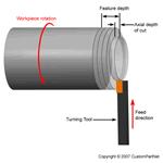
- Axial depth of cut - The depth of the tool along the axis of the workpiece as it makes a cut, as in a facing operation. A large axial depth of cut will require a low feed rate, or else it will result in a high load on the tool and reduce the tool life. Therefore, a feature is typically machined in several passes as the tool moves to the specified axial depth of cut for each pass.
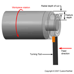
- Radial depth of cut - The depth of the tool along the radius of the workpiece as it makes a cut, as in a turning or boring operation. A large radial depth of cut will require a low feed rate, or else it will result in a high load on the tool and reduce the tool life. Therefore, a feature is often machined in several steps as the tool moves over at the radial depth of cut.
Operations
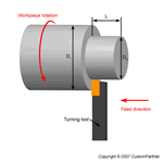
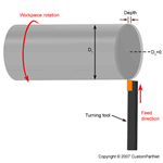
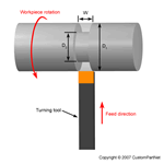
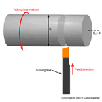
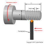
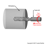
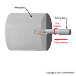
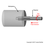
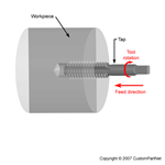
During the process cycle, a variety of operations may be performed to the workpiece to yield the desired part shape. These operations may be classified as external or internal. External operations modify the outer diameter of the workpiece, while internal operations modify the inner diameter. The following operations are each defined by the type of cutter used and the path of that cutter to remove material from the workpiece.
- External operations
- Internal operations
Equipment
Turning machines, typically
referred to as lathes, can be found in a variety of
sizes and designs. While most lathes are horizontal
turning machines, vertical machines are sometimes used,
typically for large diameter workpieces. Turning
machines can also be classified by the type of control
that is offered. A manual lathe requires the operator to
control the motion of the cutting tool during the
turning operation. Turning machines are also able to be
computer controlled, in which case they are referred to
as a computer numerical control (CNC) lathe. CNC lathes
rotate the workpiece and move the cutting tool based on
commands that are preprogrammed and offer very high
precision. In this variety of turning machines, the main
components that enable the workpiece to be rotated and
the cutting tool to be fed into the workpiece remain the
same. These components include the following:
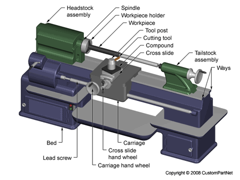
Bed
- The bed of the turning machine is simply a large base that sits on the ground or a table and supports the other components of the machine.Headstock assembly
- The headstock assembly is the front section of the machine that is attached to the bed. This assembly contains the motor and drive system which powers the spindle. The spindle supports and rotates the workpiece, which is secured in a workpiece holder or fixture, such as a chuck or collet.Tailstock assembly
- The tailstock assembly is the rear section of the machine that is attached to the bed. The purpose of this assembly is to support the other end of the workpiece and allow it to rotate, as it's driven by the spindle. For some turning operations, the workpiece is not supported by the tailstock so that material can be removed from the end.Carriage
- The carriage is a platform that slides alongside the workpiece, allowing the cutting tool to cut away material as it moves. The carriage rests on tracks that lay on the bed, called "ways", and is advanced by a lead screw powered by a motor or hand wheel.Cross slide
- The cross slide is attached to the top of the carriage and allows the tool to move towards or away from the workpiece, changing the depth of cut. As with the carriage, the cross slide is powered by a motor or hand wheel.Compound
- The compound is attached on top of the cross slide and supports the cutting tool. The cutting tool is secured in a tool post which is fixed to the compound. The compound can rotate to alter the angle of the cutting tool relative to the workpiece.Turret
- Some machines include a turret, which can hold multiple cutting tools and rotates the required tool into position to cut the workpiece. The turret also moves along the workpiece, feeding the cutting tool into the material. While most cutting tools are stationary in the turret, live tooling can also be used. Live tooling refers to powered tools, such as mills, drills, reamers, and taps, which rotate and cut the workpiece.
Tooling
The tooling that is required for
turning is typically a sharp single-point cutting tool
that is either a single piece of metal or a long
rectangular tool shank with a sharp insert attached to
the end. These inserts can vary in size and shape, but
are typically a square, triangle, or diamond shaped
piece. These cutting tools are inserted into the turret
or a tool holder and fed into the rotating
workpiece to
cut away material. These single point cutting tools are
available in a variety of shapes that allow for the
formation of different features. Some common types of
tools are as follows:
- Style A - 0 degree lead-angle turning tools
- Style B - 15 degree lead-angle turning tools
- Style C - 0 degree square nose tools
- Style D - 80 degree included angle pointed-nose tools
- Style E - 60 degree included angle pointed-nose tools
- Cutoff tools
- Form tools
The above tools are often specified
as being right or left handed, which indicates in which
direction they move along the workpiece while making a
cut.
As described in the previous section, live tooling can also be used for turning, which includes the use of mills, drills, reamers, and taps. These are cylindrical multi-point cutting tools that have sharp teeth spaced around the exterior. The spaces between the teeth are called flutes and allow the material chips to move away from the workpiece. The teeth may be straight along the side of the cutter, but are more commonly arranged in a helix. The helix angle reduces the load on the teeth by distributing the forces. Also, the number of teeth on a cutter varies. A larger number of teeth will provide a better surface finish. The cutter teeth cover only a portion of the tool, while the remaining length is a smooth surface, called the shank. The shank is the section of the cutter that is secured inside the tool holder.
All cutting tools that are used in turning can be found in a variety of materials, which will determine the tool's properties and the workpiece materials for which it is best suited. These properties include the tool's hardness, toughness, and resistance to wear. The most common tool materials that are used include the following:
- High-speed steel (HSS)
- Carbide
- Carbon steel
- Cobalt high speed steel
The material of the tool is chosen
based upon a number of factors, including the material
of the workpiece, cost, and tool life. Tool life is an
important characteristic that is considered when
selecting a tool, as it greatly affects the
manufacturing costs. A short tool life will not only
require additional tools to be purchased, but will also
require time to change the tool each time it becomes too
worn.
Materials
In turning, the raw form of the material is a piece of
stock from which
the workpieces are cut.
This stock is available in a variety of
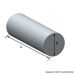
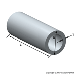
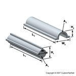
shapes such as solid cylindrical bars and hollow tubes. Custom extrusions or
existing parts such as castings or forgings are also
sometimes used.
Turning can be performed on a
variety of materials, including most metals and
plastics. Common materials that are used in turning
include the following:
- Aluminum
- Brass
- Magnesium
- Nickel
- Steel
- Thermoset plastics
- Titanium
- Zinc
When selecting a material, several factors
must be considered, including the cost, strength,
resistance to wear, and machinability. The machinability
of a material is difficult to quantify, but can be said
to posses the following characteristics:
- Results in a good surface finish
- Promotes long tool life
- Requires low force and power to turn
- Provides easy collection of chips
Possible Defects
Most defects in turning are
inaccuracies in a feature's dimensions or surface
roughness. There are several possible causes for these
defects, including the following:
Incorrect cutting parameters
- If the cutting parameters such as the feed rate, spindle speed, or depth of cut are too high, the surface of the workpiece will be rougher than desired and may contain scratch marks or even burn marks. Also, a large depth of cut may result in vibration of the tool and cause inaccuracies in the cut.Dull cutting tool
- As a tool is used, the sharp edge will wear down and become dull. A dull tool is less capable of making precision cuts.Unsecured workpiece
- If the workpiece is not securely clamped in the fixture, the friction of turning may cause it to shift and alter the desired cuts.
Design Rules
Workpiece
Features
- Select a material that minimizes overall cost. An inexpensive workpiece may result in longer cut times and more tool wear, increasing the total cost
- Minimize the amount of turning that is required by pre-cutting the workpiece close to the desired size and shape
- Select the size of the workpiece such that a large enough surface exists for the workpiece to be securely clamped. Also, the clamped surface should allow clearance between the tool and the fixture for any cuts
Features
- Minimize the number of setups that are required by designing all features to be accessible from one setup
- Design features, such as holes and threads, to require tools of standard sizes
- Minimize the number of tools that are required
- Ensure that the depth of any feature is less than the tool length and therefore will avoid the tool holder contacting the workpiece
- Lower requirements for tolerance and surface roughness, if possible, in order to reduce costs
- Avoid undercuts
Cost Drivers
Material cost
Production cost
Tooling cost
The material cost is determined by
the quantity of material stock that is required and the
unit price of that stock. The amount of stock is
determined by the workpiece size, stock size, method of
cutting the stock, and the production quantity. The unit
price of the material stock is affected by the material
and the workpiece shape. Also, any cost attributed to
cutting the workpieces from the stock also contributes
to the total material cost.
Production cost
The production cost is a result of
the total production time and the hourly rate.
The production time includes the setup time,
load time,
cut time, idle time,
and tool replacement time. Decreasing any of these time components will reduce cost. The setup
time and load time are dependent upon the skill of the
operator. The cut time, however, is dependent upon many
factors that affect the cut length and
feed rate. The
cut length can be shortened by optimizing the number of
operations that are required and reducing the feature
size if possible. The feed rate is affected by the
operation type, workpiece material, tool material, tool
size, and various cutting parameters such as the
radial depth of cut.
Lastly, the tool replacement time is a direct
result of the number of tool replacements which is
discussed regarding the tooling cost.
Tooling cost
The tooling cost for machining is
determined by the total number of cutting tools required
and the unit price for each tool. The quantity of tools
depends upon the number of unique tools required by the
various operations to be performed and the amount of
wear that each of those tools experience. If the tool
wear exceeds the lifetime of a tool, then a replacement
tool must be purchased. The lifetime of a tool is
dependant upon the tool material, cutting parameters
such as cutting speed,
and the total cut time. The unit price of a tool is affected
by the tool type, size, and material.

Truly glad to say, your post is Great.
BalasHapusKeep writing and big thanks for this post and your upcoming post.
Turning lathe machine manufacturer in China